Monday Accidents & Lessons Learned: Tools, Pressure, & a Well Control Event
Think carefully about the ratings and configuration of all tools that may be exposed to pressure during well control event response contingencies. A tool that was designed to enable casing rotation using the top drive system had a pressure limit lower than the maximum surface pressure during a well control event, and the tool also presented a mechanical internal diameter restriction that limited access. The tool was exposed to pressure when the well flowed through the shoe track after the primary cement job.
Confirm that all equipment in the well control circulating path is rated for the application
The event occurred during the cement job of 4 1/2 tubing in a nonconventional field (7500 maximum expected wellhead pressure (MEWHP) but tight properties – require fracturation to be produced).
The tubing was cemented in rotation using a casing drive system (integrated elevator/circulation device connected to top drive). The program called for a slurry displacement with an underbalance brine 1.02SG in order to leave the tubing full of clean fluid for subsequent operations.
The plug was bumped. During the tubing P-test at 7300psi – pressure dropped to 5300psi – 6 bbls were bled off to check floats – no success. Observed pressure build-up indicating link to reservoir (+/- 40psi/hour).
Unfortunately, the surface rig-up (casing drive system) was only 5K working pressure (WP) and did not allow slickline access due to a restricted Internal Diameter.
What went wrong?
The casing drive system was not identified as being part of the secondary barrier system at the end of the displacement.
Packing elements of the Casing Drive System were not qualified – only 5K WP for 7.5K MEWHP.
Mechanical barrier failure – shoe track integrity.
Displacement with an underbalance fluid disabled the primary barrier (hydrostatic fluid).
Corrective actions and recommendations
An operational risk assessment of the operation must be performed and “What If” situations evaluated (failure of shoetrack integrity).
Revision of the cement job procedure and landing string design – must incorporate a surface safety valve and possibility to run through a contingent of mechanical barriers.
All the equipment being part of the barriers (primary and secondary) must be qualified to the MEWHP.
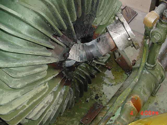
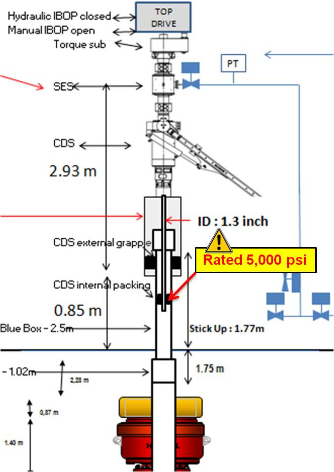
Figure 1: Surface set-up
Schematic of the pumping set-up with 5K packing elements (for a 7300psi MEWHP)
This is an IOGP (International Association of Oil & Gas Producers) Well Control Incident (WCI) Lesson Sharing 18-4, Safety Alert no. 303.
Circumstances can crop up anywhere at any time if proper and safe sequence and procedures are not planned and followed. We encourage you to learn and use the TAPROOT® SYSTEM to find and fix problems.
TapRooT® has a team of investigators and instructors with years of extensive training ready to offer assistance worldwide. We also offer ongoing support to our clients through FREE NEWSLETTERS and ROOT CAUSE TIP VIDEOS, the ROOT CAUSE ANALYSIS BLOG, and our annual GLOBAL TAPROOT® SUMMIT.
Register for one of our COURSES. We offer a basic 2-DAY COURSE and an advanced 5-DAY COURSE. CONTACT US, or call 865.539.2139 about having a course at your facility, or for further root cause analysis opportunities. We’re here to find solutions for you.